Bikes & Tools
REAMERS AND THREAD CUTTERS FOR STEEL FRAMES
The international standardization organization ISO is charged with coordination of agreements about industrial standards; one being the threads used in bicycle frames. The European norm for racing bikes is EN 14781. In the ISO standard for the bicycle industry, the British Standard Cycle thread (BSC) is still leading. In Germany this thread is called Fahrrad Gewinde (FG) and in the Netherlands NEN ; it is all identical to the English standard BSC. The French have stuck to their own metric system of measurement for years. We sometimes come across them in old Spanish, Swiss and Walloon bicycles. The bicycle manufacturers in China work for the global market; even in France we only see English sizes for new bicycles. So now we still work with measurements and measurements in inches (1inch = 25.4mm). The parts that we use to turn a frame into a bicycle also have these threads.
The most important data of a screw thread are: the diameter of the external thread D and the pitch P; further the diameter of the inner thread d, and the apex angle ɑ; this last value is usually 60°, but in the old English Whitworth (WW) standard and in the Italian bicycle threads (F) 55°. The pitch P in the metric screw thread is the number of mm's that the nut or bolt moves per revolution. In an English standard thread size, this is indicated in TPI (turns pro inch). The number of revolutions it takes to travel one inch. So the size 24 TPI is similar to our 1mm pitch, but actually 1,058mm.

FIG.1a We can measure the thread with a "thread gauge" ( a comb like tool ); here it is 1.25mm. Outer diameter D is 7.86mm; so this is a M8 x 1.25 bolt.
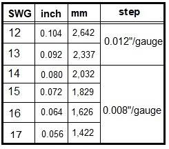
Another strange phenomenon of English sizes can be seen when displaying spoke thickness. That is done in Standard Wire Gauge (SWG): no.12 is 2.64mm and no.13 = 2.34mm, no.14= 2.03mm and no.15=1.83mm. The thinner the spoke, the higher the number. The steps between the numbers are not linear, but more or less exponential and are increased incrementally in groups; you cannot calculate them. The thread is very shallow + or - 0.25mm. The top angle in the thread is 60° and the thread always has 56 TPI from no. 12 to 15. This is a pitch of about 0.45mm; so every time the nipple tensioner goes around, the nipple moves 0.45mm. When there is tension on the spoke, this is no longer the case: the hub flange deforms, the spoke stretches, and the nipple and rim also deform; only the last piece moves 0.45mm.
In the dimensions of Italian standard thread F we often see strange mixes of metric and English sizes, such as 36x24F (=36mm x24TPI). The outer and inner dimensions are indicated in mm and the pitch in TPI; the apex angle is 55°. Mounting a headset with Italian thread on a Reynolds front fork can therefore cause minor damage due to the poor fit; usually no problem arises. Only the aluminum thread on an old rear hub can cause damage due to frequent changing of gear blocks with Italian and English threads. Officially, the English size is 1,370"x 24TPI and the Italian size is M35x 24TPI. Of course, the French have their own thread: M34.7x 1. You can screw a non-French freewheel onto it, but you are guaranteed to ruin the thread!
We often see numbers in inch fractions in the sizes of English bolts and nuts, an example: 9/16"x20 BSC; in Germany they talk about FG 14.3; the outer diameter of this thread is 14.288mm (the pitch is 1.270 mm). We find this thread on pedals. Metric threads are represented by: an M, a millimeter measurement for the outer diameter, and the pitch in mm 's. M14x 1.25 is a French thread for pedals. For the French crank, the hole is slightly smaller, so it can be tapped with an English thread. Do not mount pedals with a French thread in 9/16" BSC; this leads to loosening of the pedals and destruction of the threads.
The thread of pedals is the same as the direction of rotation of the balls in the bearing; therefore the left is a left thread and the right is a right thread; this prevents the pedals from loosening. From England the meaning of the R and L on the pedal will be clear. In France D is right and G is left, in Italy D is right and S is left, and in Spain D is right and I is left (just in case you come across Zeus pedals). Just paying close attention is also sufficient. In children's bicycles and in Fauber (one-piece) cranksets, there is usually 1/2" x 20TPI thread.
Many BSC threads are made in 24 or 26 TPI, even in large sizes. This is because, in addition to mounting, the bearings of axles, headsets and bottom brackets are also adjusted via the thread. The size 1 1/8"x26 BSC, for example, is a thread for the headset of tandems and oversize mountain bikes. Usually the headset is 1"x24 BSC, but in old English bicycles 1"x26 BSC is also found; in children's bicycles sometimes 7/2" 8" x 24TPI. French headsets are made in M25x1, sometimes M28x1 for tandems; M23x1 is found in children's bicycles.
The thread in the derailleur hanger is usually M10 x 1; Simplex had a derailleur hanger with a 9mm hole but without any thread (this is easy to tap with M10 x 1); the thread of the adjusting screw of the rear drop-out is M3 x 0.5; except for Huret, who had M3 x 0.6. The bottle holder cage thread is M5 x 0.8; mudguard fender mountings usually are M5 x 0.8 too, but sometimes M6 x 1. The thread used for a traditional Campagnolo down-tube gear lever mounting is M5 x 0.8.
The standard for bottom brackets is 1,370" x 24 BSC; in old bicycles we sometimes have a 1 3/8" x 24TPI (almost identical), but in old Raleighs or old Humbers 1 3/8" x 26TPI can also occur, with Raleigh sometimes even until the early 1970s. Older bicycles with parts from BSA, Chater Lea, Haden, etc., also use these English sizes.
The threads of bottom bracket bearing cups are provided with left-handed and right-handed threads in English cups. The French and Italian bottom brackets only have right-handed threads, and must be mounted very tightly on the drive side, to prevent unwanted accidental loosening. In French frames the thread is M35 x 1; if the drive side is equipped with a left-handed thread of M35 x 1, we are talking about a "Swiss" standard thread. In the absence of right parts, these threads are often re-tapped in the English size (a useful remedy). The Italian size designation is 36 x 24F (= 36mm x 24TPI), with right-handed thread only. If an English or French thread is damaged too far, it can be removed with a reamer and cut again with an Italian tap.

"Good tools are half the battle", they say. That is certainly the case; as struggling with poorly fitting spanners or the lack of the right monkey wrenches, often determines the time you spend on repair or maintenance. Even more annoying is the damage that can occur while working with the wrong equipment. Bad tools are made from chrome-plated soft and weak steel. It shines nicely in the store, but as soon as you put force on it, it deforms and damages not only the tools, but also your parts. Tool manufacturers with big names and good reputations provide more certainty than Chinese clones at the hardware store. Yet there are Chinese tool sets available, that are hardly inferior in quality to Gedore. There is only one place where tools can prove themselves: IN THE WORKSHOP! It is simple for the professional user; they must choose top quality equipment whenever possible. On average a tool should last about 10 years, but sometimes even quality tools wear out sooner. The professional user can write off the cost of tools for tax purposes.
At the time when Campagnolo determined the dimension standards used on racing bikes, their toolbox (large model, see FIG.1b) contained the correct tools to build a bare frame with their groupset parts into a complete bicycle. Most other manufacturers adopted the same dimensions and standards as Campagnolo, so that not many extra tools had to be purchased. The most expensive tools from the Campagnolo toolbox was the facing tools and the thread cutters; the quality was astonishing (compared to rival tools). The French company VAR and the Italian company Cobra, also made these types of toolboxes at the time. These were significantly cheaper than Campagnolo; the manufacturer Roto-Cobra had the advantage that their tools and cutters were interchangeable with Campagnolo. In any case, Roto-Cobra still supplies such tools, while Campagnolo does not. Unfortunately I was not satisfied with the quality of the cutting tools of the box FIG.2b; but they might make better stuff now?

In the bike factory, after brazing, a frame was aligned, cleaned, polished, and sprayed. Rough frames were usually not really ready to install parts on. The head tube was not always 100% perpendicular, and the inside of the head tube could be too small for mounting the headset. In addition, there could be paint residue inside the tubes and bottom bracket, which would result in the bearings being out of the correct alignment.
With the cutter number 1, the internal diameter of the head tube was increased to 30.0mm and the top and bottom faces of the head tube were flattened to precise right angles. This operation was done to the bottom and top of the head tube, so that the two halves of the headset were in accurate alignment, exactly in line with each other, and without deviation, to give true steering. The fork crown was reduced to a diameter of 26.4mm with cutter number 2, and the seating for the lower cone of the steering headset bearing was faced to be exactly perpendicular to the head tube. The steering headset bearing could now be mounted accurately. Sometimes it was also necessary to re-cut the thread of the steerer tube; there was a cutting tool in the toolbox for this purpose.
The threads were then cut into the bottom bracket with the thread tap number 3. Paint and brazing residues were removed, to fit into the bottom bracket correctly. After this, two guide bushes (4) were screwed into the bottom bracket, with two special auxiliary keys, and the bottom bracket shell could be faced perpendicular to the newly cut bottom bracket threads with surface cutting tool number 4. Of course there were other thread cutters and guide bushings for English, French, and Italian frames (but only one kind was included in the box, and there was no spare space inside the toolbox for any other pieces!)

The derailleur hanger thread was tapped with M10 x 1; With M3 x 0.5 the thread of the adjusting screws in the rear drop-out was cleaned, and with M5 x 0.8 the thread of the bottle carriers was cleaned, as were the threads on the down-tube gear lever mounts -- which were also M5 x 0.8. Unfortunately these small taps were not standard in the Campagnolo toolbox. Then an adjustable diameter reamer was used on the inside of the top of the seat tube to prevent any scratches on the seat post (unfortunately this tool was also not included in the Campagnolo toolbox).
The front and rear fork ends were checked for alignment and spacing, with the alignment checking tool. With a long and straight steel ruler, the rear forks were checked to be sure that they were properly centered in line with the bottom bracket, the seat tube, and the head tube. Finally the rear derailleur hanger can be checked for alignment using the special Campagnolo tool which screws into the derailleur hanger, the swinging end of the tool is compared to the position of the rim on a rear wheel (obviously the reference wheel must be absolutely true and accurate) which has been inserted into the frame (making sure that the axle fixing is tight, so the wheel does not move), with an equal spacing all the way around the wheel rim, the derailleur hanger is proven to be not out of line, and perpendicular to the wheel axle. After that, the frame was completely ready to install. The pressing of the head cups was done with some other attachments, via mill number 1. This was cumbersome using the Campagnolo tool; VAR and Hozan had finer tools for this task.
In the 1970s and 1980s, there was already a lot of special monkey wrenches needed, for example for dismantling the many different types of freewheels . Unfortunately, this trend has become worse and worse over time. Campagnolo's market share has shrunk considerably and with it, the tendency to follow their particular standard. Each manufacturer uses its own standards now. I have a box full of monkey wrenches from Shimano in particular, which were once necessary for assembly or maintenance when a new groupset was introduced. In the next groupset, (a year later), other tools had to be purchased, on and on.....Campagnolo hardly makes tools anymore. Instead of the superb quality of Campagnolo tools, there are now many inferior quality tools, made in the Far East at a low price, to be used a few times before they break!
A modern supplier of cycling tools is Cyclus. These tools are more versatile and affordable than the old Campagnolo stuff, and that is why my old Campagnolo toolbox has a new owner. The fetish character of the Campagnolo brand ensures that this old equipment still yields decent prices. Of course, Cyclus cannot match the quality of Campagnolo, but to give an idea of how expensive that Campagnolo toolbox was in 1980: it cost six net monthly salaries for the average bicycle mechanic. In 2010, the Cyclus toolbox was available with the same options, but it only cost less than a monthly salary of a bicycle mechanic.
The current carbon and aluminum frames are better finished than the old-fashioned steel frames. Many dimensions of frames and parts have changed over the years.
Cyclus and Parktool supply dozens of wrenches with modern sizes for modern frames, which are unfortunately necessary for today's variations in dimensions for the bottom brackets and headsets; for Cyclus see FIG.3 and 4 .
Parktool for headsets : https://www.parktool.com/blog/repair-help/standardized-headset-identification-system
Parktool for brackets: https://www.parktool.com/blog/repair-help/bottom-bracket-identification More about brackets: https://wheelsmfg.com/bb-standards


FIG. 3 Cyclus fitting tools for brackets. FIG.4 Cyclus reamers and cutters, for modern head sets.
BALL BEARINGS
The purpose of bearings is to support rotating shafts. These bearing axes can be used either "axial" (in the longitudinal direction of the axis) or "radial" (perpendicular to the axis). There are 2 groups of bearings: plain bearings and rolling bearings; In bicycles we mostly work with rolling bearings. We often encounter variants of the ball bearing in headsets; sometimes there are needles or rollers instead of balls. The old-fashioned adjustable "cup and cone" construction of bicycle bearings (actually a single-row angular contact bearing) has largely been replaced by the use of groove ball bearings, mounted inside a sealed unit. These are not adjustable and that means that they must be replaced when worn (usually as an entire unit). For the cartridge bearing unit, the installation time in the factories is shorter, and easy to automate (the most important advantages, at least economically).
See the NSK guide to the common types of bearing that are available -- but be aware that bicycles sometimes use unique non-standard bearings, that are not generally available.
In FIG.5 we see that the groove ball bearing can take forces from all directions; which is not the case with the other two.
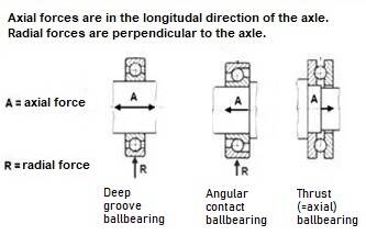


FIG.5 Bearings and forces they can absorb.
FIG.6 A SKF bearing hammer toolset
FIG.7 A bearing press with many bushings.
The choice for groove ball bearings is cost savings; installation and replacement is easier and takes less time, but it requires a slightly different way of working and different tools. In general, we use a slight interference fit to secure each bearing unit in position, installation is done by applying pressure to the inner and/or outer ring of the bearing via an auxiliary bushing. Applying that pressure can be done via a press (FIG.7) or a hammer, for example from the SKF hammer tool-set (FIG.6); This hollow plastic hammer contains loose grains. This gives a pleasant, recoil-free, and controllable tap.
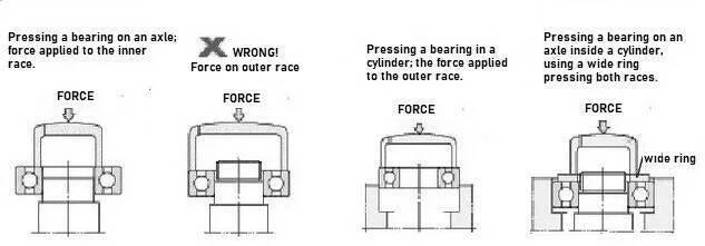
FIG.8 Mounting a bearing using a bushing (note the placement of the bush onto the bearing)
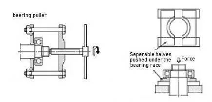
FIG.9 Removal of a bearing, using a bearing puller and a draw plate.
The pressure-plates shown in FIG.8 and FIG.9, show that the force applied to a bearing must be on the ring which is subjected to friction during pressing. The pressure should not be exerted to the other ring, to prevent the pressure being transmitted via the balls, which might cause damage to the bearing unit. Unfortunately, the designers of hubs, for example, are not always concerned with maintenance problems. In any case, when disassembling (tapping out), the bearings must be properly checked and replaced if necessary (noting the cause of any damage to the bearing -- such as a damaged seal-disc).
The fit of the bearing to the axle (on the inside), and into the housing (on the outside), must be a slight interference fit. Depending on the diameter, of the order of thousandths or hundredths of a millimetre. If a bearing does not fit properly, particularly if it is loose, it can cause damage, or be dangerous, an example of this is if a headset bearing is loose, the steering may be unpredictable and dangerous, which is another reason to check that the correct bearings have been fitted in the correct way (including in the correct orientation).
In industrial applications, interference fits can be graded and classified, but this is not the case in the bicycle industry, where standards are much more casual and random.
For ISO industrial standards see the NTN guide (2203E) to the fitting tolerances of bearings (Limits and Fits tables).
The most important dimensions of the bearing are outer ring size, inner ring size, and bearing width. The quality of the materials used, and therefore life expectancy, cannot always be properly estimated. Big names (such as SKF) provide more certainty, but there are different quality classes. Unfortunately, the prices of the better classes of bearings are significantly higher. The highest class available is something for space technology, (where sending a mechanic is not an option); the price is often corresponding.
Some more detailed information from one of the major bearing suppliers (particularly for cars) https://medias.schaeffler.co.uk/en/bearing-data
A good way to check the dimensions of a bearing, is to use a digital vernier caliper measuring instrument, from a reputable manufacturer.
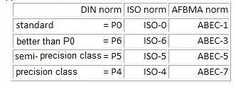
Quality standards for bearings are related to the fitting system, but the designation is not identical. Standard bearings are designated ISO-0. Certain constructions require higher precision (such as for high speeds). Bearings are therefore available for this purpose with higher precision (such as to reduce any wobbling of a fast rotating shaft). ISO standards have also been laid down in tables for dimensional and motion accuracy. Tolerance classes can also be found here, both in ISO - (0,6,5,4) and in the German DIN - (P0, P6, P5, P4), and American AFBMA standard (given as ABEC-1-3-5-7). We will encounter the standard P5, ISO-5, and ABEC-5 at most in the top segment of the market. Sometimes we see so-called "ABEC-12" popping up at AliExpress; a fantasy marketing standard, without any real specification.
It is important to realize that unfortunately nowadays there are some counterfeit bearings on the market, so if at all possible it is better to try to source bearings from a reputable dealer. If you have any doubts, check the packaging and documentation supplied with the bearing, and search on the Internet for information about counterfeits. Generally counterfeiting is more of a problem with high value parts, such as in aerospace, but some bicycle part have been counterfeited, in the past. Bearings often have identification markings on them, always check them before fitting, if possible.
In recent years so called "ceramic" bearings have been marketed by the cycling industry, sometimes at extraordinary prices, and sometimes with extraordinary claims! In reality only the balls have been replaced with ceramic ones, the rest of the bearing unit, including the raceways, is still made out of steel. So while the ceramic balls may be extra hard, the surfaces that they run on are the same as traditional steel bearings. Sometimes it has been claimed that these "ceramic" bearings have extra low friction, but as most of the friction in a bearing unit comes from the seals and the grease, changing the type of balls used is not so important, so for most riders steel bearings are a far more sensible choice, especially as they are far cheaper to replace.
Ceramic ball bearings are made from Silicon Nitride material, which is less dense than steel, so the balls are lighter weight, this means at high rotation speeds there is less outward force pushing away the lubricating grease than with steel balls. In reality cyclists only pedal at about 100 RPM, and bicycle wheels might only rotate at 1000 RPM on a fast descent, so this advantage of ceramic balls is not so important, compared to the parts inside a jet engine which might rotate at more than 10000 RPM. Ceramic ball bearings have some other desirable properties, including being corrosion resistant, and being heat resistant (very useful inside a hot jet engine). See 2012 SKF document (evolution#1) about the development and use of ceramic ball bearings.
There are counterfit SKS bearings on the market, see video below!
Bicycles are often used in muddy and wet conditions, (such as off-road mountain biking), because of this the seals used on the bearing are important -- good quality bearings will have good quality seals. Unfortunately seals can become damaged and worn, so they should be regularly checked, and replaced if necessary. If a replacement seal cannot be sourced, then the entire bearing unit may need to be replaced.
In an effort to improve the sealing of the bearing, some brands of headset have completely filled the space around the ball bearings with a plastic spacing ring, so making it more difficult for dirt to enter the bearing unit. Unfortunately these types of bearings can have high friction, so they are not well suited for use in hubs or bottom brackets.
The seals on a bearing can be a major source of friction for the bearing, because of this for short indoor track races the bearing seals can sometimes be removed to reduce friction.
The grease used inside the bearing can also be a source of friction, so sometimes oil will be substituted for grease, in an effort to reduce friction, but the oil can quickly run out of the bearing, so the lubrication must be frequently checked. For outdoor use, (especially in bad weather conditions), a high quality grease is far more suitable than oil. Many sorts of grease are commonly available from the car industry, as well as the usual branded greases from the big bike brands.
Information from a major bearing supplier, showing some of the many different types of bearing seal available : https://medias.schaeffler.co.uk/en/sealing-of-the-bearing-positions
See NTN document (3017E)for information about wear and damage to bearings, how to troubleshoot problems, and bearing maintenance issues.
THE TORQUE WRENCH
Until 1990, most bicycles were made of steel. The mechanic simply secured all the bolts and bolts sufficiently. This practice is outdated with modern carbon and aluminum frames. To mount parts safely and damage-free, you must work with a torque wrench.
The moment we use to secure a bolt depends on the length of the lever and the force we exert. Moment is: force x arm. So if we have a longer key, we need to apply less force for the same moment. If you don't have a torque wrench, but you do have a handheld weighing scale to determine the weight of the suitcase at the airport, you can actually also measure the torque. Suppose you have to tighten a bolt with 10 Nm; you have a ring wrench of 20 cm. Then you have to put on your handheld weighing scale up to 50N (= 5kg) to get 50N x 0.2m = 10Nm.

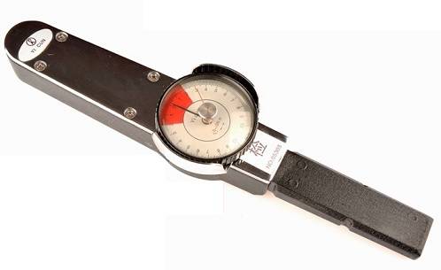
FIG.1a The torsion arm torque wrench; a bending steel rod, where we read the torque on the dial.
FIG.1bA variant, in which the lever operates a dial gauge, via compression springs.
There are several types of torque wrenches. The lever type (torsion arm, see FIG.1a) is the simplest. In fact, the arm bends over the entire length when a force is applied. Unfortunately, these types of torque wrenches can be difficult to read, and require a lot of space when used; which is often just not there. During normal use, this sort of meter remains accurate, and we can use it to calibrate other torque wrenches. The one shown here is suitable for up to 300Nm; We don't encounter that high a torque level in bicycles. With modern carbon and aluminum bicycles, the torques used for small bolts are between 4-10Nm. Cranksets may sometimes have 50-70Nm. Please note whether the parts manufacturer recommends using grease or a retaining liquid. Prescribed torques are often given as "dry". If you use grease or a locking fluid, tightening is easier, and there is too high a tension on the bolt.

FIG.2 The "click" torque wrench. By tightening the spring in the handle, we set a value that produces a "click" sound when it reaches the preset value.
Most “click type” torque wrenches, as we can see in FIG.2. Over time, these keys may differ slightly from the set value to be read. The cause of that decline lies in the construction of the torque wrench. The tool works with a spring that is tensioned, via the screw handle with vernier. That spring presses on a ball, that fits into a hole, in the movable head of the key. In the photo we see the rotating shaft with retaining ring under the head. When the ball shoots out of the hole, you hear a "click". We then have to stop energizing immediately, because the connection is not broken, so we could just tighten the bolt further. The small torque wrench has a 1/4" head, and can be set up to a maximum of 25 Nm. The large torque wrench has a 1/2" head, and can be set up to a maximum of 200 Nm. Using an adaptor, we can also provide both heads with a 3/8" head, depending on the socket set used. Obviously a 1/4" head is weaker than a 1/2" head, and can only withstand smaller torque levels. While a small tool may be useful to fit into a small space, for safe operation it is better not to overload a tool, especially a calibrated torque wrench.
The spring in the handle is intended to keep a little pressure. If the pressure disappears, parts of the mechanism can become loose or defective. So it is better not to turn the spring all the way back to zero, but keep the tool with, for example, 10% of the maximum torque value as a setting. When first put into use, it is recommended to extend to the maximum torque setting a number of times (>5), to push away any burrs or dirt inside the tool. Then the tool is worn-in.
If the torque wrench tools are frequently used, it is recommended to check their accuracy every month, by comparing them with a torsion arm torque wrench, or electronic torque wrench. This way you can prevent the tightening torques from slowly becoming lower and lower, and being inaccurate.

FIG.3a A nice set of caps, with a torque wrench.

FIG.3b The black ring is the vernier for fine adjustment; the lower ring is for the coarse adjustment, and for the fixation of the chosen value.

FIG.4a Intermediate adaptor piece, with electronic measurement.
A separate measuring piece turns a regular socket wrench into an electronic torque wrench. This measurement works with strain gauges, and is accurate for a torque wrench. They are not available in most shops, but they are available in several variants via AliExpress online. For example, choose a measurement of up to 15Nm with a 1/4" head, and a 75Nm with a 3/8" head. If you use a meter with a large range, this is at the expense of the accuracy of the low measured values. They are sensitive, and are often used.
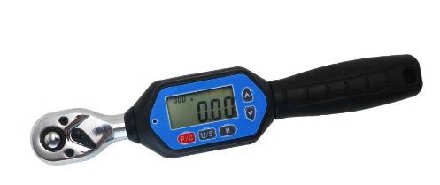
FIG.4b A full-fledged electronic torque wrench. These give a beep when the set value is reached.
The designer prescribes a certain tightening torque. This depends on the construction, and the materials used; it is always lower than the maximum possible torque for that bolt, there must be a safety margin, such as to take account for possible corrosion.
The head of a bolt sometimes indicates the steel quality used with an ISO code, for example "8.8" or "12.9". The number ahead of the decimal point is 1% of the tensile strength, in N/mm². The number behind the decimal point is ten times the yield stress/tensile strength. It is recommended to use the manufacturer's supplied bolt; if you replace a bolt, it must have at least the same quality class as the original part. Once a bolt is rotated over the yield stress limit, turning becomes easier and easier, until complete fracture occurs.
Because the failure of a bolt could result in a crash, it is vital that bolts are not over-tightened and damaged, if there is any doubt -- inspect the parts, if you are not sure about the safety of a part, then it is wiser to replace it if possible. Remember that professional riders have their bicycles inspected, checked and serviced after any crash, modern racing bicycles are often made with lightweight parts, which frequently only have a limited service life, there is always a trade-off between lightweight and reliability, fragile components must be treated with respect, they are not designed to last forever.
Clamping carbon seat posts and steering parts is difficult, because the part will sometimes still move after the maximum tightening torque has already been reached. It is recommended that the item be removed, and that a carbon mounting paste be used between the parts, to increase the friction between them -- the opposite effect to a lubricant. This type of friction-paste contains a fine abrasive that improves grip, without damaging the parts. For example: https://tacx.com/nl/product/carbon-montagepasta/
TOOLS FOR BICYCLE WHEELS


The wheel truing jig, the nipple tensioner key, and the wheel hub aligner dishing stick, form the tools for the wheel builder. The nipple tensioner is the cheapest part, but don't try to save money on it. If the steel of the tool is not hard enough, the nipples can be damaged and deformed -- which can make truing a wheel very difficult. The 'Spokey' model of nipple key is cheap, and usable for up to No.14 size nipples. The hub aligner dishing stick is the least critical tool; I am very satisfied with my low price Minoura tool.
I used cheap wheel truing jigs for many years (see FIG.1). I then treated myself to a second-hand VAR 'Preciray' (see FIG.2 and https://www.youtube.com/watch?v=H7b2ZXAZwVw&t=102s ; perhaps I should have used such a tool earlier. Nowadays there are even nicer ones, for example 'P&K Lie'; beautiful but very pricey: https://www.wheelfanatyk.com/blog/category/pk-lie-truing-stand/ (see FIG.3b)
Via Wheels2build you can also order tools, including a Chinese model, (inspired by the P&K Lie wheel truing jig), for more than 200 Euros (FIG.3a), also found at AliExpress.

For wheel building nowadays you also need a spoke tension meter. An affordable and widely used one is the Park-Tool 'TM-1'. The operation of this gauge (FIG.4) is as follows: The device contains a spring with a certain bias tension. You keep the spoke located in two places (at the bottom of the dotted line) and release the spring. The spring presses the third contact point in the middle -- between the two pegs, (FIG.6) outward over the height h max. 5mm -- usually the effective measuring area, (spoke tensions between 500N and 1500N, are limited to approximately 2mm). The meter will move over part of the scale at the top of the tool (the scale is divided into 50 tenths of a mm). The designated number reading from the scale is then compared with a table (FIG.5), in which the spoke thickness and shape are incorporated.
In fact, the accuracy of this type of meter is very limited. To improve this slightly, I read the measured values at 0.5 (estimate). I then average the numbers on the conversion table of (FIG.5).
The resistance of the spring should not be too great (e.g. 10-20N), so as not to affect the result of the measurement too much.

A handy auxiliary tool is included for measuring spoke thickness. With the data spoke thickness, and measured value, we can look up the spoke tension. Especially if we measure relatively (per spoke in a wheel), we can work well with this. To absolutely measure the tension of each spoke, the meter must be calibrated. Park-Tool offers the option of having the meter re-calibrated, but the cost of sending the meter back to Park-Tool in the USA is not financially worthwhile, with a price of 80 Euros for a new spoke tension meter. The spring tension of the meter could decrease with frequent use, which is likely to reduce the accuracy of the meter.
This is for checking the spoke tension of a complete wheel. When entering the readings, the WTA app provides a radar graph of the wheel, (similar to FIG.10c).
https://www.parktool.com/blog/repair-help/wheel-tension-balance-app-instructions
For less than 15 Euros (incl. shipping), I bought a Chinese meter via Ebay (see FIG.7a). This is a calibrated copy, that can be used with the Parktool tables, and the WTA-app.

There are manufacturers that offer much more accurate spoke tension meters, like DT-Swiss; in FIG.8 and FIG.9 we see two models, an analog FIG.8 (approximately €500) and a digital meter FIG.9 (approximately €1000). At these prices these tools are something for top racing mechanics, professional wheel builders, and wheel manufacturers. The measured values of the digital DT device can be processed directly into the computer (via a USB cable). Hozan FIG.10 (about €480) also provides such meters. AliExpress and Ebay also have many copies of these meters for sale, for a fraction of this money. My DT copy (FIG.9a) was beautifully finished, with a digital dial indicator, and was delivered to my home for only €50 (1/20 of the cost of a DT digital meter). But the supplied measured value table is a joke!
Fatal mistake! Such a Chinese copy is not a bargain! You don't just buy a thing, but a whole measuring system. Quality has a price, see the tables from DT: http://www.dtswiss.com/Products/Proline.aspx

I made a spoke pull bench myself, for calibration of the spoke tension meter. If the meter on the tensile testing machine indicates 100kg of load, the value according to the table of the Chinese DT copy meter says more than 140kg (force). There is an adjustment screw on the meter, to adjust the spring tension, but tightening the spring has no effect; as the spring is too short! Despite the seemingly beautiful finish, its usability as a measuring device for a bicycle shop is limited to relative tension in a wheel, and not the absolute tension!
Anyone who has a factory built wheel with a spoke breakage, should be able to adjust the wheel to tension the spokes according to the original value of the factory data, but to do this the spoke tension measurement has to be reliable. The usability of the measuring instrument is largely determined by the accuracy of the supplied tables!
Creating those tables yourself is very time consuming, and you still have to first make a tensile testing machine (or buy one, which can be expensive).
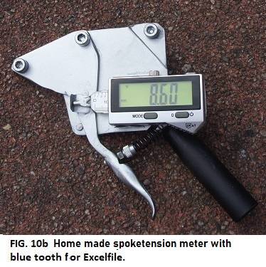

This picture (FIG.10b) is a home constructed spoke tension meter, with Bluetooth connection. When you use an associated Excel file on the computer (see FIG.10c), the light orange fields can be filled in by the user; you register the spoke tension meter as a Bluetooth keyboard. At the touch of a button (at the top right of the meter's display), the measured value (mm) is entered into the Excel file, and is automatically converted into Newtons. The data from the spoke tension meter appears in a table, (where you enter separately, first side A, and then side B). These values are also shown in a radar graph.
I had already written an Excel file for the Parktool 'TM-1' spoke tension meter as an exercise. You can see what that looks like in the picture below. This is not a real wheel, but an example of how a 28 spoke wheel, with No.13 spoke is displayed on the computer. A printout can be included as a quality inspection with a new spoked wheel. A new wheel, with good quality parts, must be able to be made within limits of + or - 10% of the average spoke tension (minimum 90% tension, and maximum 110% tension).
Making those Excel files for different spoke thicknesses, butted spokes, and various numbers of spokes per wheel, is a lot of work; and it is especially boring! If a dozen ascending values for a type of spoke are known, I determine a calculation formula in Excel with curve fitting, to translate the measured mms into Newtons (or, if necessary, old-fashioned kilogram force).
If you work with the Parktool 'TM-1' spoke tension meter, it is better to use the online WTA app; it has some extra options.

The stocks of spokes available have continued to decline; everything has a long delivery time, and is only available in larger order numbers. It is becoming increasingly difficult to get a different spoke size. Professional spoke thread rolling machines, such as Cyclus, cost approximately 3000-4000 Euros. Morizumi is a Japanese variant, and certainly just as expensive; the American manufacturer Phil Wood makes one, which is even more expensive. The cutting plates of Phil Wood, Morizumi, and Cyclus, probably last 50,000 to 100,000 spokes; replacement cutting plates for the Morizumi machine cost around €250, Phil Wood's around €500, and Cyclus €1200. These expensive machines do provide a nice constant thread length and constant thread depth, unlike my cheap Hozan machine (FIG.11), which does not produce consistently good results, unfortunately.
Hozan now has an electric machine in production, see FIG.13 (approximately €900) with an improved head (type 'C-706'; €70 via Ebay); it also fits the roller 'C-700' of FIG.11. Anyway, the quality of the thread is determined by the roller head, which is only mediocre. The roller of FIG.11 has a really lousy bearing, and the spoke clamp is bizarrely annoying. It has now been replaced by a home-built one, with a suspension clamp that is "open" as standard, but still with the 'C-706' roller head. Also Hozan has a new roller with an improved clamp 'C-702' (€170 via E-bay). I am making a roller based on the Morizumi cutting plates; unfortunately it is difficult to achieve the fine tolerances needed to get a nice even rolled thread.

.
< FIG.14 Some tools for building wheels.
Here we see a number of tools for spoking wheels. The pliers (on the left) are a spoke cutter from VAR. They cut everything, but squash the spoke flat. If you want to roll threads on the spoke, the spoke must be ground or filed around, so as to fit well inside the thread rolling tool. A spoke ruler, such as the Cyclus, (at the bottom of the picture) is indispensable. The black roll (in the left centre) contains all kinds of grooves, that hold an aero bladed spoke, to prevent the spoke from twisting while tightening the nipple. For tightening nipples I have a number of spoke keys, (as you can see at the top).
Anyone who builds a lot of wheels, (especially if they are in series production), can save time with the help of the screwdriver with a rotating handle. The blade of the screwdriver contains an extra tip of 2mm. This way you can tighten all the nipples the same distance, while lacing the wheel. With the right spoke length, there is not really any tension on it, and the rising spoke end presses out the blade of the screwdriver from the tool, so preventing any further rotation of the nipple. Anyone who wants to mechanize even further can use an electric screwdriver, with a Cyclus bit attachment, where the ejection-pin depth of the tool is adjustable (very neat, very handy).
The pliers (at the bottom right of the picture) make a "Z" bend in the end of the spoke, in place of the enlarged head on a J-bend spoke. Using this tool we can create a spoke to length, by first cutting off the head, and using the "Z" bend of the bayonet as a new end of the spoke. An advantage is that this type of spoke can be mounted without removing the gear cassette. We can even leave the wheel in the frame; usually these are emergency solutions for a spoke breakage on the road. It is also a cheap and fast way to make old bicycles usable again. But one should not expect this to be a good quality solution for shortening spokes, where rolling a new thread is a far better thing to do (with the right equipment).
When building wheels, it is recommended to lubricate the nipples with a drop of linseed oil. There are also special products available (such as 'SpokePrep' or 'SpokeFreeze'). Use of these products is necessary to prevent the nipples from loosening, especially at spoke tensions above 1000N. Factory wheels often contain nipples with a hexagon on top, to reduce that vulnerability. Usually such nipples are used on wheels made using robot machines. There are also nipples that are pre-processed with internal micro capsules of glue, to fix the spoke in place and stop it from moving. There are several different methods of locking a nipple in place, volume wheel makers seek out cheap solutions, that can be used easily on a fast production line, with robots.
A section about wheel making robots can be found at the end of page 17: Wheels & spokes.