BRAKES
If we want to reduce speed of a vehicle, we have to reduce the amount of energy present in the system. This usually happens in a controlled manner through friction, which is converted into heat. There are two places on the wheel where we can reduce speed: on the hub and on the rim. The first bikes had no brakes; the speed was low and the pedals were fixed on the wheel axle. By counteracting the rotation of the axle, you could reduce speed. Fixies and track bikes still use this method. It takes some getting used to, but bicycle couriers and track cyclists often master this technique very well.
Around 1870 the bicycle starts participate more in traffic, and we see a rear brake appear. In its most primitive form, a kind of spoon, which by pulling a cable on the handlebars, puts a pad on the rim of the wheel (FIG.1,2,3). As long as we have a fixed gear bike (Highwheeler or Safety), these brakes are just assisting. The invention of the freewheel (1898) made these brakes insufficiant.
In FIG.2 & 3 we see a front and rear brake from 1898. The front brake FIG.3 works with a push rod (plunger brake). Alas it does not work when you have a flat tire, a disadvantage. The rearbrake uses a handle, a complicated system of rollers and a cable. A rotating handgrip was used to transmit the power to the brake.The invention of the inner- and outer cable combination by Bowden in 1897 (FIG.4), made that outdated.
Before 1900 threewheelers often used a band brake FIG.5; a leather strap, which wraps around a drum attached to the hub body. This idea dates back to the carriage era.
This brake type was the standard on city bikes in Japan for decades; it was even used on the bottombracket axle of fixed gear bikes.
The plunger frontbrake-coasterbrake combination, was often used in German city bikes until the end of the 60's. The Dutch authorities thought just a coaster brake was enough.

FIG. 1 (1870)

FIG.5 Bowden (1905)

FIG.2 (1898) FIG.3 (1898)

FIG.6 (1898)
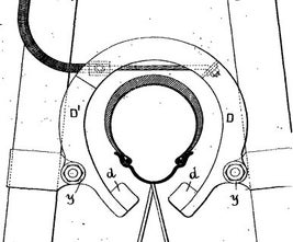
FIG.4 Bowden (1897)
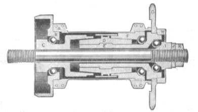
FIG.7 New Departure (1900)
In the nineties of the 19th century, with the development of the safety bicycle came the coaster brake. The first coaster brakes like Hay&Willits FIG.6 were not that effective. While backpedalling the cone nr14, is pushed against the brake lining nr19. New Departure (FIG.7) and Eadie quickly developed better ones. Because the traditional flanges are not available with the New Departure design, they chose straight spokes and mounting blocks on the hub.

FIG.9 Raleigh


FIG.12a (1908)

FIG.12b (1987)
With the development of the pneumatic tire, plunger brakes become less effective; the air in the tire limits the force that is exerted. Instead of braking on top of the tire, new brakes (FIG.9) press on the underside of the rim, by brake blocks mounted on a horseshoe shaped brake. This pull brake is usually operated by a rod system. The braking effect in the rain is poor. The firm of Raleigh has used these brakes until the seventies; we still see these brakes on oriental clones. Around 1905, the BSA company made a pull brake (FIG.10) that was operated by a clutch on the bottom bracket axle, but you combine the disadvantages.
By making the rim a bit higher, you could press the blocks on the side. Early versions of this brake can be seen in FIG.12a. If the brake pads are actuated from the center (FIG.12a), we call this a centerpull brake and on the side (FIG.11) we call it a sidepull brake. The centerpull of FIG.12a is a special design by Teurtroy from 1908; we see very few of those. Campagnolo brought one on the market in 1987 (FIG.12b), they were so problematic that the pro-racers didn't want to use them. It is bizarre that the few brakes in circulation are now worth a lot of money.

.FIG. 13 Mafac 1955

..FIG. 14 Resilion 1939

FIG.15 Weinmann

FIG.16 Altenburger Synchron
The centerpull brake has two pivots; both brakeblocks move simultaniously to the rim.. As a result, the wear of the blocks is even. With the Mafac brake of FIG.13 and the Resillion of FIG.14, the pivot point is close to the brake pad. Due to the circular movement of the brake and wear of the brake pad, it is wise to check regularly if the brake surface still fits properly on the rim. Otherwise there is a risk that the brake pad holder can slide under the rim. The centerpull brake was standard on end 50's and 60's racing bikes.
The Altenburger Synchron (FIG.16) has two pivots but is operated from the side; both brake parts move the brakepads to the rim. This is also the case with the Weinmann from FIG.15 , but here the cable operates a screw-vise to get more pressure on the brakeblocks.
From mechanical physics, we know that the ratio of "pivot point to braking surface distance", and "pivot point to braking force contact point" must be small (preferably less than 1), in order to properly utilize the force the rider exerts on the brake lever. The brake of FIG.12a scores much better than that of FIG.11. The version of a brake caliper in steel is stiffer than that of an aluminum brake caliper; those things feel sometimes like you're squeezing a sponge.
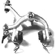


FIG.17 Shimano Dura Ace 1975
.FIG.18 Shimano Tourney 1978
.FIG.19 Shimano 600 Parapull 1982
FIG.20 Campagnolo Delta 1988
The Shimano Tourney brakes of FIG.18 are bad; the center pull is the less bad one. They were often used on cheap bikes in the 70/80's ; from the end of the eighties those cheap bikes were fitted with the far better cantilevers we see in FIG.13 or V-brakes like FIG.22.
Around 1970 Campagnolo made a sidepull brake that was good enough for racing. Many other brake manufacturers followed the fashion and in FIG.17 we see the Shimano Dura Ace version. The mechanical ratio's of the brake are much better than those of the sidepull Tourney brake in FIG. 18 and the brake is stiff enough. The Parapull from FIG.19 had a less ideal mechanical ratio and was dumped after a year.
The racingbike brakes after 1995 are often dual pivot FIG.21; a variation on the Altenburger from FIG.16. The better mechanical ratio is more profitable than the disadvantage of the uneven deployment of the brake parts.
Another way to improve the power of a brakesystem is using hydraulics. Shimano used a single cylinder acutuating both brake parts in 1972 (FIG.24). Magura had a sturdy design using two cylinders in the brakepad holder (FIG.23). This had more commercial succes than the Shimano brake. Their racing brake design looked a lot like the Shimano brake of 1972.
.FIG.21 Shimano sidepull

.FIG.22 Tektro V-brake

FIG.23 Magura Hydraulic 1988
FIG.24 Shimano Hydraulic 1972

FIG.25a Renault 1902

FIG.25b Sturmey Archer

FIG.25c Dinex "drum brake" 1980
The first patented drumbrake (brakeshoes dry in the drum) was from the Frenchman Renault in 1902 (FIG.25a). While braking, you pull the brake lever nr 7 to the left and this turns the rectangular brake key nr 6 (black) horizontal, wich pushes the brake shoes nr 1 against the drum.. The first Sturmey Archer hub with a drum brake was the KB from 1918. FIG.25b is a later version SA BR/C.
The Dinex brake (FIG.25c) is really only found on the Bridgestone / Kyobashi bikes. The brake is a cross between a drum brake and a band brake and comes from Japan. A brake shoe is pressed against the drum from the inside and the outside. Diving into the archives, we see a U.S. patent of mr. Nield from 1900, who designed a similar type of brake (see patent at the bottom of the page).
The Rollerbrake by Shimano FIG.26 & FIG.27 is a development from the nineties for citybikes. Rainproof and it doesn't need much maintenance. The construction is the same as the old Sachs Torpedo coasterbrake, but that used the rollers as freewheel. The Shimano rollers are pushed outside bij the black camwheel that rotates as you pull the brakelever. It is a variation on the drumbrake and will replace much bandbrakes in Japan.
Though the first diskbrakes were made in 1902 (FIG.28), it took till the end of the thirties to get usable production brakes (not for bicycles!). The Shimano hydraulic disc brake from 1975 (FIG.29), shows that this manufacturer has worked on this technique for a long time; long ahead of many others of it's bicycle industry competitors. The diskbrake matured in the MTB scene in the early 2000's and is taking over the market. In the cheaper part of the market, they are not hydraulic but cable operated.

FIG.26 Shimano Rollerbrake

FIG.27 Shimano Rollerbrake

FIG.28 1902 Lanchester Diskbrake.


FIG.29 Shimano disc brake (1975)
FIG.30 JFOYH Hydraulic disc brake set
FIG.31 Shimano mechanical disc brake (2010)
The Shimano disc brake of FIG.29 was also available in a cable version; in 1974 they had even taken the trouble to apply for a patent for it. A 2010 version of such a mechanical brake is shown in FIG.31. Only one side of the caliper moves when you brake. Overall, the hydraulic brakes are far superior. End seventies Phil Wood marketed a very expensive hydraulic brake that did not perform well. Not all inventions succeed.
Modern hydraulic brakes have at least 2 pistons, which press on the disc from both sides. The more expensive versions even have four pistons, especially in wet weather a clear improvement. Discs come in sizes 140, 160 and 180mm. Attempts to agree on a standard of 160mm were unsuccessful. The attachment to the hub also has a number of variants. The situation around the brake linings is even more embarrassing. You may soon have to buy new brakes, because no suitable blocks are available.
ABOUT BRAKING
Most of the braking energy is converted into heat. This is often noticeable during steep descents. Rims and brake pads get hot. If you ride with tubulars, you can experience that the glue softens and the tubular gets twisted. In the extreme case, it can even slide off the rim. Especially in the front this is dangerous because of jamming in the front fork. Hub brakes like roller brakes sometimes have extra surface to dissipate that heat (see FIG.27). Drum brakes often also have cooling fins. Disc brakes get very hot; the hydraulic oil in the brake system usually has a reservoir to facilitate expansion.
Brake pads for rim brakes are made in thousands of shapes and sizes. Unfortunately, you only find out the quality when you use them. Koolstop brake pads have a good name rightly so. There were special blocks for steel rims; you were not allowed to use those on aluminum rims, because they ate them. Nowadays the same is true with carbon rims; there you also have to use special blocks. Among others by Campagnolo (see patent from 2007).
One of the fads of the 1970s were the double brake levers. They were touted as "safety levers", but in the rain it was downright dangerous. This picture FIG.32 comes from a patent application of Dia-Compe from 1966. It was all the rage in the 1970s.
When the derailleur is in common use after the war, there is already a Mr. Navet in 1946 who combines brake- and shift handles (FIG.33). That is widely used after 1990 when the Shimano Total Integration design hits the market. (FIG.34) Campagnolo struggeled to keep up with the developments, but the current handgrips for 140mm hydraulic disc brakes and 12 wireless shifted gears, are really upto date (see FIG.35).

FIG.32 Dia-Compe 1966

FIG.33 Navet 1946
FIG.34 Shimano STI Di2

FIG.35 Campagnolo Hydraulic 12sp.
The friction resulting from braking can be used to amplify braking action by sliding the brake pad toward the rim at an angle (see FIG.36). It does indeed work, braking takes less effort. On the other hand, the difference between braking in dry weather and braking in the rain becomes much greater, and that is not appreciated.
In addition to power brakes, attempts have also been made to limit braking force to the front wheel and thus prevent "flying over the bar". This is mechanically relatively easy to achieve by letting the rear brake operate the front brake. In FIG.37, they mounted a pivoting sprung auxiliary fork, on which the rear brake is mounted. When the brake is actuated via the blue cable, the spring stretches and operates the inner cable attached to the auxiliary fork. This will operate the front brake via the red cable (1991). I designed a similar system can be used with hub brakes, by attaching the brake lever rotatably to a spring-loaded cylinder FIG.38 (1984). Although a German company (Biria 142) has marketed such a product in 1994, it has had little success.
E-bike ATB's can be fitted with electronic ABS a by the firm Bosch , see 2008 patent below (https://www.youtube.com/watch?v=9JT2aBv7stg&t=411s ).
Shimano filed their's in 2019, see below.....

FIG.36

FIG.37 (1991)

FIG.38 (1984)
The most important brake designs were there before 1910. The development and improvement of brakes has often been less important than marketing and fashion. The legal minimum demands were often far less than technically possible. The legislator and bicycle factories have hardly been taking the safety of the cyclist seriously. Even in cycle racing, in the years before the war until the mid-fifties, there were hardly any improvements for the brakes of racers. No wonder Wim van Est ended up in the ravine.
Strange brakes: http://www.blackbirdsf.org/brake_obscura/road.html Very strange brakes: http://www.blackbirdsf.org/brake_obscura/mtb.html